
Page 56 - Demo
P. 56
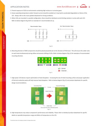
APPLICATION NOTES TECHNICAL NOTES54www.SunLEDusa.comConventional PadDo not use this area for electrical contactImproved Pad DesignSolder MaskSolder Points (Cu)Cu-areaAPPLICATION NOTESThe technical notes in this catalog are subject to change without notice.6. Mounting direction of SMD components should be placed perpendicular to the direction of PCB travel. This will ensure the solder wets on each lead simultaneously during reflow and prevent shifting of LEDs. Refer to below diagram (Fig.11) for examples of recommended mounting direction.8. High temperatures may reduce component%u2019s performance and reliability. Please refer to individual product datasheets for specific details on operable temperature range and effects of temperature on the LED.7. High-power LED devices require optimization of heat dissipation. Increasing the size of metal mounting surface and proper application of thermal conductive paste will help improve heat dissipation. Refer to below diagram (Fig.12) and product datasheets for specific design recommendations.Fig. 11Fig. 123. Prevent exposure of LEDs to environments containing high moisture or corrosive gases.4. Excess operating temperature and/or forward current should be avoided as it may lead to accelerated degradation or failure of the LED. Always refer to the most updated datasheet for driving conditions.5. When LEDs are mounted in a parallel configuration, there should be individual current-limiting resistors in series with each LED. Refer to below diagram (Fig.10) for an example of a recommended set up.Fig. 10
