
Page 55 - Demo
P. 55
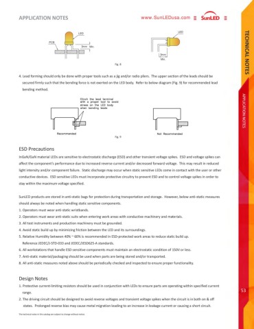
APPLICATION NOTES TECHNICAL NOTES53www.SunLEDusa.comThe technical notes in this catalog are subject to change without notice.APPLICATION NOTES4. Lead forming should only be done with proper tools such as a jig and/or radio pliers. The upper section of the leads should be secured firmly such that the bending force is not exerted on the LED body. Refer to below diagram (Fig. 9) for recommended lead bending method.InGaN/GaN material LEDs are sensitive to electrostatic discharge (ESD) and other transient voltage spikes. ESD and voltage spikes can affect the component%u2019s performance due to increased reverse current and/or decreased forward voltage. This may result in reduced light intensity and/or component failure. Static discharge may occur when static sensitive LEDs come in contact with the user or other conductive devices. ESD sensitive LEDs must incorporate protective circuitry to prevent ESD and to control voltage spikes in order to stay within the maximum voltage specified.SunLED products are stored in anti-static bags for protection during transportation and storage. However, below anti-static measures should always be noted when handling static sensitive components.1. Operators must wear anti-static wristbands.2. Operators must wear anti-static suits when entering work areas with conductive machinery and materials.3. All test instruments and production machinery must be grounded.4. Avoid static build up by minimizing friction between the LED and its surroundings.5. Relative Humidity between 40% ~ 60% is recommended in ESD-protected work areas to reduce static build up. Reference JEDEC/J-STD-033 and JEDEC/JESD625-A standards.6. All workstations that handle ESD sensitive components must maintain an electrostatic condition of 150V or less.7. Anti-static material/packaging should be used when parts are being stored and/or transported.8. All anti-static measures noted above should be periodically checked and inspected to ensure proper functionality.ESD PrecautionsDesign Notes1. Protective current-limiting resistors should be used in conjunction with LEDs to ensure parts are operating within specified current range.2. The driving circuit should be designed to avoid any forward/reverse voltage while the LED is in OFF state in order to prevent electrochemical migration which may cause damage to the LED.Fig. 9Fig. 8Min.Min.PCB3mm3mmLED LED
